Index
- File Systems vs DBMS
- 2-tier Architecture vs 3-tier architecture
- What is Schema?
- Three Levels of Abstraction / Three types of Schema
- Data Definition Language (DDL)
- .Data Manipulation Language (DML)
- Data Independence
- Integrity Constraints
- Entity Relationship Model
- Types of attributes in ER model
- Types of Keys in relational database
- Types of relationships in ER Model (not the ones you’re thinking of)
- 3. Implementing One-to-One Relationships in the Relational Model
- One to Many Relationship
- Many-to-Many relationship
- Data Models
File Systems vs DBMS
1. Historical Context and Basic Definitions
-
File System Background:
Before DBMSs became common, data was managed using file systems. In the 1970s and even today on personal computers, file systems organize data in a hierarchical structure using files, folders, and subfolders. -
Introduction of DBMS:
While file systems work well for a single user or local data management, DBMSs emerged as a solution for more complex, centralized, and multi-user data management needs.
2. Data Access and Retrieval Efficiency
- File System Limitations:
With file systems, when a user needs to retrieve a small piece of data, they often have to load an entire file. For example, retrieving a 1 KB detail from a file might involve reading a large file (the speaker uses an exaggerated example of 25 GB) which is inefficient in terms of memory and processing. - DBMS Advantage:
A DBMS, on the other hand, allows users to query the server (using SQL) so that only the exact piece of data needed is sent over the network. This leads to faster, more efficient data retrieval and lower memory usage on the client side.
3. Abstraction from Physical Data Storage
- File System Requirements:
In a file system, accessing data requires knowledge of file attributes like name, location, and permissions. The user must know where and how the data is stored. - DBMS Abstraction:
With DBMS, users interact with data through queries without needing to know the physical location of the data. This abstraction simplifies data access, especially in client-server architectures where data resides on a remote server.
4. Concurrency and Multi-user Environment
- Challenges with File Systems:
File systems do not have built-in protocols to handle multiple users accessing or modifying the same file concurrently. This can lead to data inconsistencies when many users attempt to read or write at the same time. - DBMS Concurrency Control:
DBMSs incorporate robust protocols to manage concurrency. They handle multiple transactions (for example, the speaker cites IRCTC handling thousands of transactions concurrently) by managing different scenarios like read-read, read-write, write-read, and write-write operations to ensure data consistency.
5. Security and Role-Based Access Control
- File System Security:
In traditional file systems, security is basic and managed at the operating system level. There is limited control over who can access specific parts of data beyond file-level permissions. - Enhanced DBMS Security:
DBMSs offer role-based access control, meaning different users (such as students, faculty, or administrators) can have tailored access to data. This layered security approach ensures that users see only the data they are authorized to view, which is critical in systems like banking or educational institutions.
6. Data Redundancy and Integrity
- Redundancy Issues in File Systems:
With file systems, it’s easy to accidentally store the same data multiple times (redundancy), especially if similar files are saved under different names. - Data Integrity in DBMS:
DBMSs enforce data integrity through constraints like primary and foreign keys. These constraints help prevent data duplication and ensure that only unique, consistent data is stored in the database.
7. Overall Conclusion and Real-World Applications
- Client-Server and Web Applications:
The lecture emphasizes that while file systems are adequate for simple, individual data storage, modern applications—especially those using client-server architectures like IRCTC, Flipkart, Amazon, or Google—rely on DBMSs. DBMSs are superior in handling large-scale, concurrent, and secure data operations. - Summarized Advantages of DBMS:
To sum up, DBMS provides faster and more efficient data retrieval, abstracts the complexity of data storage, supports concurrency control, enforces robust security through role-based access, and maintains data integrity by reducing redundancy.
2-tier Architecture vs 3-tier architecture
https://www.youtube.com/watch?v=VyvTabQHevw&list=PLxCzCOWd7aiFAN6I8CuViBuCdJgiOkT2Y&index=4
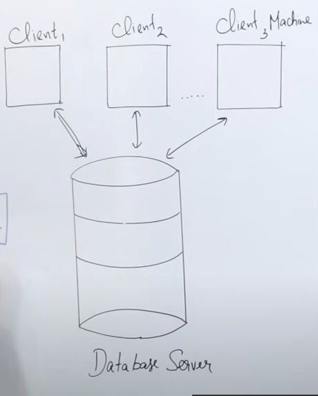
2-Tier Architecture
Definition
- “Tier” means “layer”, so 2-tier architecture consists of two layers:
- Client Layer – The user’s machine running an application with an interface (UI).
- Database Server Layer – A server that processes and executes queries.
How it Works
- The client machine has an interface (API) that allows users to interact with the database.
- The connection between the client and server is established via JDBC-ODBC (database connectivity).
- The client sends a query (e.g., fetching data), which the database server processes and returns to the client.
- Example: If a user writes a Java program to fetch data, the request is processed by the database server, converted into machine language, executed, and then data is sent back to the client.
Real-Life Examples
- Indian Railways Reservation System
- If you go to a railway station and book a ticket at the counter, the person at the counter uses a client machine to enter details.
- The database server retrieves seat availability and processes the booking.
- Banking System
- When you withdraw money from a bank, the clerk enters your details into their client machine.
- The database server verifies your balance and processes the transaction.
Advantages & Disadvantages of 2-Tier Architecture
- Advantages:
- Simple and easy maintenance (since only authorized clients interact with the database).
- Disadvantages:
- Not scalable – If too many users access the database simultaneously, it fails.
- Security issue – The client interacts directly with the database, increasing risk.
- Due to these issues, modern systems have shifted to 3-tier architecture.
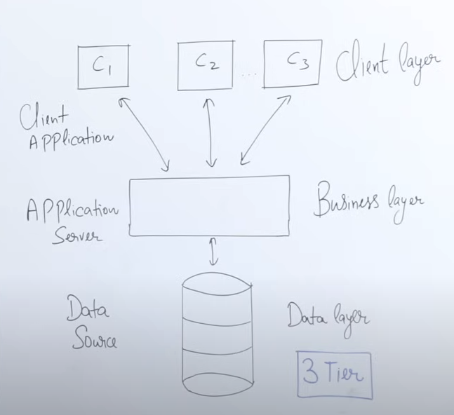
3-Tier Architecture
Definition
- 3-tier architecture introduces an extra layer:
- Client Layer (same as before)
- Business Layer (new) – Processes queries before sending them to the database.
- Database Layer (same as before)
How It Works
- The client interacts with an application interface (e.g., IRCTC website, banking app).
- Instead of sending the query directly to the database, it first goes to the business layer.
- The business layer processes and optimizes the query, reducing the database server’s load.
- This prevents the database server from becoming a bottleneck (too many requests slowing it down).
- Users no longer need to manually write queries – instead, they use checkboxes, buttons, and forms, and the application generates queries automatically.
Advantages of 3-Tier Architecture
- Scalability – The business layer handles user requests, reducing the direct load on the database.
- Security – The client does not interact directly with the database, preventing unauthorized access.
- Comparison with Cloud Computing – Similar to cloud systems like Gmail, where users don’t know where the data is stored but can access it seamlessly.
- Faster Data Processing – The business layer prepares optimized queries, so the database server only handles precise, filtered requests.
Conclusion
- 2-tier architecture is simpler but has security and scalability issues.
- 3-tier architecture is more secure, scalable, and efficient.
- Modern applications like banking systems, e-commerce, and cloud services prefer 3-tier architecture.
Schema and it’s architectures
What is Schema?
1. Definition and Concept
- Logical vs. Physical Representation:
- Logical Representation: A schema represents the structure of the database in a logical format. This includes the way data is organized into tables (or relations in an RDBMS) and the relationships between different entities.
- Physical Representation: Although data is physically stored in files on a hard drive or server, the schema abstracts this physical storage into a more user-friendly, logical view.
2. Illustration with Entities
-
Example – Student Entity:
- A “student” entity, which might have attributes such as:
- Roll Number
- Name
- Address
- These attributes form columns in a table, which together represent the schema for students.
- A “student” entity, which might have attributes such as:
-
Example – Course Entity:
- Similarly, a “course” entity could include attributes like:
- Course ID
- Course Name
- Course Duration
- These elements create a structured table that defines the schema for courses.
- Similarly, a “course” entity could include attributes like:
-
Multiple Tables:
- A schema can consist of one or several tables that are related to each other, collectively defining the overall structure of the database.
3. Three-Schema Architecture Context
- Conceptual Schema:
- In the three-schema architecture, the middle layer is the conceptual schema. This layer represents the logical view of the entire database, independent of the physical storage details.
- It’s at this layer where the schema defines how users view the data, in the form of tables and relationships.
4. Implementation Using SQL
- SQL and DDL Commands:
- While a schema can be depicted as a diagram or a paper representation, its actual implementation in a DBMS is carried out using SQL.
- Data Definition Language (DDL):
- Commands such as
CREATE TABLE,ALTER TABLE, andDROP TABLEare used to define, modify, and remove schema structures.
- Commands such as
- These SQL commands translate the logical schema (the design of tables, columns, data types, and constraints) into an actual database structure that the DBMS can manage.
5. Summary
- Schema as a Blueprint:
- A schema is essentially the blueprint of the database, showing how data is organized logically.
- It provides a structured way to view and manage data, ensuring consistency and clarity when data is accessed or modified.
- From Design to Implementation:
- While the schema starts as a logical, diagrammatic representation, it is eventually implemented using SQL in the form of DDL commands, making it a tangible part of the database system.
Three Levels of Abstraction / Three types of Schema
https://www.youtube.com/watch?v=5fs1ldO6B5c&list=PLxCzCOWd7aiFAN6I8CuViBuCdJgiOkT2Y&index=6
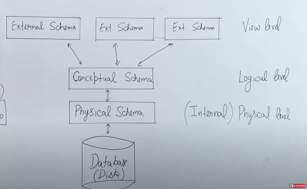
The three-schema architecture in a Database Management System (DBMS) is a conceptual framework that separates how data is viewed by users, logically organized, and physically stored. This separation not only simplifies design and maintenance but also provides data independence—changes in one layer do not necessarily affect the others. Here’s a detailed breakdown:
1. External Schema (View Level)
-
Definition:
The external schema defines the way individual users or user groups view the data. This level is all about providing a tailored perspective of the data based on user needs. -
Key Points:
- Personalized Views: Different users (or applications) can have customized views of the database. For example, in a university management system, a student might see only their personal records (grades, attendance, fee details), whereas a faculty member might have access to a broader set of data including class rosters and student performance.
- Security and Authorization: The external schema helps enforce security by ensuring that users see only the data they are permitted to view. It limits exposure of sensitive data and hides unnecessary details.
- User-Centric Presentation: By abstracting the complexities of the underlying structure, the external schema provides an easy-to-understand view that supports efficient querying and reporting.
-
Example:
When you log in to a webmail service like Gmail, the interface you see is the result of the external schema. It presents your emails, contacts, and settings without exposing how the emails are actually stored or managed behind the scenes.
2. Conceptual Schema (Logical Level)
-
Definition:
The conceptual schema provides a unified, logical view of the entire database. It defines the structure of the data (tables, columns, relationships, constraints, etc.) without being tied to how the data is physically stored. -
Key Points:
- Logical Organization: This level specifies the entities (e.g., Student, Course) and relationships (e.g., enrollment, course assignments) in the database. It is here that the overall design or “blueprint” of the database is created.
- Data Integrity and Constraints: The conceptual schema includes rules and constraints such as primary keys, foreign keys, and other integrity constraints that ensure the data remains accurate and consistent.
- Abstraction from Physical Storage: Users and applications interact with the database based on this logical design, while the details of how data is actually stored are hidden in the lower layer.
-
Example:
In a relational database, the conceptual schema might define a “Student” table with columns likeRoll_Number,Name,Age, andAddress, along with relationships to other tables likeCourseorDepartment. This design is often represented using Entity-Relationship (E-R) diagrams before actual implementation.
3. Internal Schema (Physical Level)
-
Definition:
The internal schema describes the physical storage of data on the hardware. It deals with the actual implementation details such as file structures, indexes, data blocks, and storage allocation. -
Key Points:
- Physical Data Storage: This level determines how data is stored on disk drives, including the organization of data in files, the use of indexes for faster retrieval, and methods for efficient data access.
- Performance Optimization: Database administrators (DBAs) work at this level to optimize performance by choosing the best storage techniques and configuring how data is physically arranged.
- Mapping from Logical to Physical: There is a mapping process that translates the logical constructs defined in the conceptual schema into the physical structures managed by the internal schema. This allows changes in physical storage (e.g., moving to a new type of disk) without impacting the logical view.
-
Example:
While the conceptual schema might represent data in terms of tables and relationships, the internal schema might store this data in a set of files or blocks on a disk. Indexes and other structures are implemented to enhance retrieval speed without the end-user noticing these details.
Data Independence and the Role of Mapping
-
Data Independence:
One of the major benefits of the three-schema architecture is data independence.- Logical Data Independence: Changes to the internal schema (physical storage) do not affect the conceptual schema. For instance, you can change the way data is stored on disk (e.g., switch from one storage system to another) without changing the logical design.
- External Data Independence: Changes to the conceptual schema have minimal impact on the external schema. This means that even if you alter the logical structure (e.g., add new relationships or tables), you can maintain the same user views.
-
Mapping:
The DBMS uses mapping functions to bridge the gaps between these levels:- External-to-Conceptual Mapping: This defines how different user views (external schemas) are derived from the overall logical design.
- Conceptual-to-Internal Mapping: This outlines how the logical structures are implemented physically, ensuring that performance optimizations at the physical level do not compromise the logical view.
Conclusion
The three-schema architecture is fundamental to modern database systems because it cleanly separates user interaction, logical design, and physical storage. This layered approach:
- Enhances Security: By controlling access through external schemas.
- Improves Flexibility and Maintenance: Through data independence, changes in one layer have minimal impact on the others.
- Optimizes Performance: DBAs can fine-tune physical storage without affecting how users or applications access data.
Data Independence
1. What Is Data Independence?
-
Definition:
Data independence means that changes made at one level of the database system do not affect other levels. It ensures that users and application programs continue to work smoothly even when the underlying data structure or storage details change. -
Goal:
The primary goal is to make the user “independent” from the physical details of how data is stored or how the logical structure is organized. This provides a level of transparency so that, regardless of internal modifications, the application’s functionality remains consistent.
2. The Three Levels of Schema Architecture
Recall that the three-schema architecture separates the database system into three distinct layers:
-
External Schema (View Level):
- Purpose:
Provides customized views for different users or applications. - What It Hides:
It hides both the logical (conceptual) and physical details. For example, although a table might contain many columns, a view might show only the relevant ones (say, just Name and Age for a student). - User Experience:
When you access your Gmail account or a university management system, you see only the data you’re authorized to view. The complexity of underlying data storage is completely hidden from you.
- Purpose:
-
Conceptual Schema (Logical Level):
-
Purpose:
Represents the entire logical structure of the database. This includes definitions of tables, relationships between them, attributes, and integrity constraints such as primary and foreign keys. -
What It Hides:
It abstracts the details of physical storage from the end users. For example, you might have a “Student” table with columns like Name and Age (and even Mobile Number if added later), but the user’s view might remain unchanged. -
Flexibility:
Changes can be made at this level—such as adding or deleting columns—without affecting the external view, thanks to logical data independence. This means application programs do not need to be rewritten when the logical structure changes.
-
-
Physical Schema (Internal Level):
-
Purpose:
Specifies how data is actually stored in the system. This includes file structures, indexes, storage location, and the use of different data structures (like stacks, linked lists, etc.). -
What It Hides:
The physical details (such as whether data is stored on hard disk 1 or moved to hard disk 2, or the type of indexing used) are hidden from both the conceptual and external layers. -
Adaptability:
Modifications like moving the database or changing the storage method (for performance reasons) are made without any impact on the conceptual schema. This is known as physical data independence.
-
3. Types of Data Independence
-
Logical Data Independence:
-
Concept:
Changes at the conceptual level (like altering the table structure or adding a new column) do not affect the external views. -
Example:
Imagine a student table that originally shows only Name and Age. If a new column (Mobile Number) is added for certain users, those who aren’t meant to see it continue to view just the original two columns, because the view (external schema) is kept independent. -
How It’s Achieved:
Through the use of views (virtual tables), the DBMS can present a consistent interface to users even if the underlying logical design changes.
-
-
Physical Data Independence:
-
Concept:
Changes at the physical level (like moving files to a different disk or changing the indexing method) do not affect the conceptual schema. -
Example:
If a database is moved from one hard disk to another or if the DBMS changes the file structure for performance improvements, the structure of the tables and relationships as defined in the conceptual schema remains unchanged. -
Benefit:
Applications and users continue to access data normally, without any disruption, because the logical view they work with is not affected by physical alterations.
-
4. Why Is Data Independence Important?
-
User Transparency:
Users interact with their data through an application or a web interface without needing to know the complexities of data storage or the logical organization. They get a consistent and familiar view regardless of any changes happening behind the scenes. -
Maintenance and Evolution:
Database administrators (DBAs) can optimize and modify the physical storage for performance or cost reasons, or update the logical design to reflect new requirements, without forcing application developers to rewrite or adjust the user-facing programs. -
Seamless Upgrades:
In dynamic environments—like web applications, university management systems, or large-scale platforms such as Google—even if substantial changes occur in the way data is stored or logically organized, users experience continuous service without disruption. -
Real-World Example:
Consider Gmail: the underlying physical storage or indexing mechanisms may be optimized or changed over time, and even the logical structure might evolve. However, as a user, you only see your consistent inbox and mail view, thanks to data independence.
Integrity Constraints
1. Purpose of Integrity Constraints
-
Ensuring Data Quality:
When you create a database and define its tables (or schema), you need to insert data in an organized manner. Integrity constraints are the rules that make sure the data inserted is valid and meaningful. They prevent arbitrary or incorrect data from being entered into the database. -
Maintaining Consistency:
These rules ensure that once data is inserted, updated, or deleted, the overall integrity of the database remains intact. In other words, integrity constraints help maintain the accuracy, consistency, and reliability of the data over time.
2. Domain Constraints
-
Definition and Role:
Domain constraints relate to the attributes (columns) of a table. When you design a table—say, for students or employees—you specify various attributes like name, age, mobile number, etc. Each attribute is assigned a specific data type (e.g., integer, character, string), which defines the domain of valid values. -
Practical Example:
If an attribute such as age is defined to accept only positive integers, an attempt to insert a value like -5 would violate the domain constraint. Similarly, if a mobile number is expected to be exactly 10 digits long, a value with eight digits would be rejected.- Check Constraints:
To enforce such rules, you can use check constraints in SQL. For instance, a check constraint can specify that the age must be greater than zero or that the length of the mobile number must be exactly 10.
- Check Constraints:
3. Primary Key Constraints
-
Definition and Importance:
Every table should have at least one primary key. The primary key is a unique identifier for records in a table and must have the properties of uniqueness and non-nullability. This means no two records can share the same primary key, and the primary key field cannot have a null value. -
Ensuring Uniqueness:
By enforcing the primary key constraint, the database guarantees that each record can be uniquely identified. This prevents duplicate entries and maintains the overall integrity of the dataset. -
Additional Notes:
Sometimes, other unique constraints (related to candidate keys) are also defined for attributes such as Aadhaar numbers, license numbers, phone numbers, or email IDs, ensuring that those values remain unique across the table.
4. Referential Integrity Constraints
-
Definition:
Referential integrity constraints deal with the relationships between tables, particularly in parent-child table scenarios. They ensure that data in the child table corresponds to data in the parent table. -
How It Works:
For example, if you have a master (parent) table and a related child table, any record in the child table must reference a valid record in the parent table. If an attempt is made to insert a record in the child table that doesn’t have a corresponding parent record, the database will reject it to preserve data integrity. -
Implementation Using Foreign Keys:
Foreign keys are used to enforce referential integrity. They act as a link between related tables, making sure that relationships remain consistent and preventing orphaned records.
5. Overall Importance of Integrity Constraints
-
Data Validity:
The primary role of integrity constraints is to ensure that only valid, high-quality data is stored in the database. -
Error Prevention:
By defining rules (such as domain, primary key, and referential integrity constraints), the database system can automatically prevent errors—like inserting an invalid age or a mismatched foreign key—from occurring. -
Long-Term Data Reliability:
Integrity constraints help in maintaining the overall reliability and consistency of the database. This is crucial for applications that rely on accurate data, such as university management systems, banking applications, or any system where data accuracy is paramount.
Types of Keys in relational database
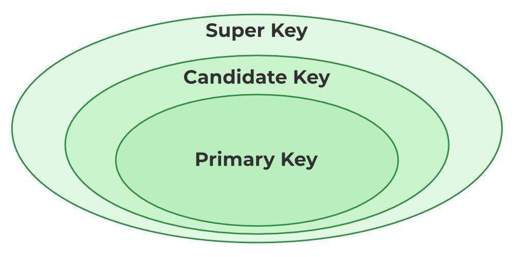
- Super Key
- Candidate Key
- Primary Key
- Foreign Key
- Super Key
1. Super Key
The set of one or more attributes (columns) that can uniquely identify a tuple (record) is known as Super Key. For Example, STUD_NO, (STUD_NO, STUD_NAME), etc.
- A super key is a group of single or multiple keys that uniquely identifies rows in a table. It supports NULL values in rows.
- A super key can contain extra attributes that aren’t necessary for uniqueness. For example, if the “STUD_NO” column can uniquely identify a student, adding “SNAME” to it will still form a valid super key, though it’s unnecessary.
Example table:
| STUD_NO | SNAME | ADDRESS | PHONE |
|---|---|---|---|
| 1 | Shyam | Delhi | 123456789 |
| 2 | Rakesh | Kolkata | 223365796 |
| 3 | Suraj | Delhi | 175468965 |
Consider the table shown above.
STUD_NO+PHONE is a super key.
2. Candidate Key
The minimal set of attributes that can uniquely identify a tuple is known as a candidate key. For Example, STUD_NO in STUDENT relation.
- A candidate key is a minimal super key, meaning it can uniquely identify a record but contains no extra attributes.
- It is a super key with no repeated data is called a candidate key.
- The minimal set of attributes that can uniquely identify a record.
- A candidate key must contain unique values, ensuring that no two rows have the same value in the candidate key’s columns.
- Every table must have at least a single candidate key.
- A table can have multiple candidate keys but only one primary key.
Example : STUD_NO is the candidate key for relation STUDENT.
3. Primary Key
There can be more than one candidate key in relation out of which one can be chosen as the primary key. For Example, STUD_NO, as well as STUD_PHONE, are candidate keys for relation STUDENT but STUD_NO can be chosen as the primary key (only one out of many candidate keys).
- A primary key is a unique key, meaning it can uniquely identify each record (tuple) in a table.
- It must have unique values and cannot contain any duplicate values.
- A primary key cannot be NULL, as it needs to provide a valid, unique identifier for every record.
- A primary key does not have to consist of a single column. In some cases, a composite primary key (made of multiple columns) can be used to uniquely identify records in a table.
- Databases typically store rows ordered in memory according to primary key for fast access of records using primary key.
4. Foreign Key
A foreign key is an attribute in one table that refers to the primary key in another table. The table that contains the foreign key is called the referencing table, and the table that is referenced is called the referenced table.
- A foreign key in one table points to the primary key in another table, establishing a relationship between them.
- It helps connect two or more tables, enabling you to create relationships between them. This is essential for maintaining data integrity and preventing data redundancy.
- They act as a cross-reference between the tables.
- For example, DNO is a primary key in the DEPT table and a non-key in EMP
1. Introduction to Foreign Keys
- Key Concept – Referential Integrity:
The primary role of a foreign key is to maintain referential integrity. In simple terms, referential integrity ensures that relationships between tables remain consistent. For example, if a record in one table refers to a record in another table, that referred record must exist.
2. The Role of Foreign Keys in Maintaining Integrity
-
What is Integrity?
Integrity in databases means that the data is accurate and consistent. In a well-designed database, all related data must be in agreement—there should be no contradictory or mismatched information. -
Example of Referential Integrity:
Consider a university:- Student Table (Referenced Table): Contains details such as roll number, name, and address. The roll number here acts as the primary key.
- Course Table (Referencing Table): Contains course details along with a column for student roll numbers (the foreign key).
The foreign key in the course table must match an existing roll number in the student table. If a student’s record is removed from the student table while still referenced in the course table, it creates an inconsistency—a loss of referential integrity.
3. Operations and Their Impact on Referential Integrity (Important)
A. Operations on the Referenced (Base) Table
-
Insertion:
- Inserting new data (e.g., a new student record) into the student table usually does not cause any integrity issues.
-
Deletion:
- Potential Problem: If you delete a student record from the student table (base table) while that student’s roll number is still referenced in the course table, the foreign key constraint is violated.
- Solutions:
- Manual Deletion: First, delete the corresponding record from the course table before deleting from the student table.
- ON DELETE CASCADE: Automatically deletes all related records in the referencing table when a record in the base table is deleted.
- ON DELETE SET NULL: Sets the foreign key in the referencing table to NULL when the referenced record is deleted.
- Default Behavior: If no action is specified, many systems use “ON DELETE NO ACTION” or “RESTRICT,” which will throw an error if you try to delete a record that is referenced elsewhere.
-
Updation:
- Changing a primary key value (for example, updating a roll number in the student table) can lead to inconsistency if the referencing table isn’t updated simultaneously.
- Solutions:
- ON UPDATE CASCADE: Automatically updates the corresponding foreign key values in the referencing table.
- ON UPDATE SET NULL: Sets the foreign key to NULL if the referenced value changes, though this is less common when the foreign key is also a primary identifier in the referencing table.
- Potential Violation: Direct updates without proper cascading rules may break the relationship, leading to orphaned records.
B. Operations on the Referencing Table
-
Insertion:
- When inserting a record into the referencing table (like adding a new course record), the foreign key value provided must already exist in the referenced table (student table).
- Violation Scenario: If you try to insert a record with a roll number that does not exist in the student table, the database will prevent the insertion to maintain integrity.
-
Deletion:
- Deleting a record from the referencing table (for instance, a course record) generally does not affect the referential integrity of the base table. Removing the reference means there is no longer a dependency, so no violation occurs.
-
Updation:
- Updating values in the referencing table must ensure that any change to the foreign key still corresponds to a valid primary key in the referenced table.
- Violation Scenario: Changing the foreign key to a value that does not exist in the base table would violate referential integrity.
4. Summary of Key Points
-
Core Function:
The foreign key is critical for ensuring that relationships between tables (e.g., a student and the courses they take) remain consistent. This is what is meant by “referential integrity.” -
Automatic Solutions:
The video explains automatic methods like:- ON DELETE CASCADE: Deletes dependent rows automatically.
- ON DELETE SET NULL: Replaces the deleted key with NULL to maintain consistency.
- Similar options exist for update operations, such as ON UPDATE CASCADE.
Data Definition Language (DDL)
1 Role of DDL
- DDL statements define, alter, and drop structures (schema objects) in the database: tables, views, indexes, triggers, and more.
- Typically require higher privileges (e.g., DBA or schema owner).
2 Common DDL Commands
-
CREATE
- Usage: Create a new table, view, index, or other object.
- Syntax (Table):
  CREATE TABLE students (
student_id INT PRIMARY KEY,
name       VARCHAR(50) NOT NULL,
major      VARCHAR(50),
dob        DATE,
CONSTRAINT chk_major CHECK (major <> '')
);- Extras: Constraints like
PRIMARY KEY,FOREIGN KEY,CHECK,UNIQUE,NOT NULL.
-
ALTER
-
Usage: Modify the structure of an existing table or other objects.
-
Syntax:
ALTER TABLE students ADD COLUMN email VARCHAR(100) UNIQUE; -
Possible Actions: Add/drop columns, rename columns, change data types, add constraints.
-
-
DROP
-
Usage: Delete a table, view, or other object from the database.
-
Syntax:
DROP TABLE students;
-
-
TRUNCATE
-
Usage: Quickly remove all rows from a table, resetting it to empty without logging each row deletion.
-
Syntax:
TRUNCATE TABLE students; -
Note: TRUNCATE is typically faster than
DELETEwithout aWHEREclause.
-
-
RENAME (DBMS-dependent)
-
Usage: Rename database objects.
-
Syntax (Oracle example):
RENAME students TO student_info;
-
3.3 Constraints in DDL
- PRIMARY KEY: Ensures unique identification of rows.
- FOREIGN KEY: Maintains referential integrity between tables.
- UNIQUE: Prevents duplicate values in a column.
- CHECK: Enforces a condition on values in a column (e.g.,
salary > 0). - NOT NULL: Disallows NULL values in a column.
.Data Manipulation Language (DML)
1. Role of DML
- DML commands manipulate data within the structures defined by DDL.
- Includes operations that read, insert, update, and delete data.
2. Common DML Commands
-
SELECT
-
Usage: Retrieve data from tables/views.
-
Key Clauses:
WHERE(filtering)GROUP BY(aggregation)HAVING(filtering aggregated results)ORDER BY(sorting)JOIN(combining rows from multiple tables)
-
Example:
SELECT s.student_id, s.name, c.course_name
FROM students s
JOIN enrollment e ON s.student_id = e.student_id
JOIN courses c    ON e.course_id = c.course_id
WHERE s.major = 'Computer Science';
-
-
INSERT
-
Usage: Add new rows to a table.
-
Example:
INSERT INTO students (student_id, name, major, dob)
VALUES (101, 'Alice', 'Computer Science', '2002-05-14');
-
-
UPDATE
-
Usage: Modify existing rows.
-
Example:
UPDATE students SET major = 'Information Technology' WHERE student_id = 101; -
Caution: Without a
WHEREclause, all rows in the table are updated.
-
-
DELETE
-
Usage: Remove rows from a table.
-
Example:
DELETE FROM students WHERE student_id = 101;
-
3. Transaction Control (Often Considered Part of DML)
- COMMIT: Save all changes made during the current transaction.
- ROLLBACK: Undo changes made during the current transaction.
- SAVEPOINT: Set a marker within a transaction to which you can roll back partially.
Key Insight:
- DML typically operates under the ACID properties (when transactions are involved).
- Proper use of transactions ensures data consistency and integrity.
Data Models
Entity Relationship Model
https://www.youtube.com/watch?v=gbVev8RuZLg&list=PLxCzCOWd7aiFAN6I8CuViBuCdJgiOkT2Y&index=15
1. Purpose of the ER Model
-
Conceptual Design:
The ER model is used to create a conceptual (or logical) view of the data. Just like an architect creates a blueprint before building a house, database designers use the ER model to map out what data needs to be stored, how different data elements are related, and what constraints exist before any actual implementation is done. -
Flexibility for Changing Requirements:
When discussing requirements with stakeholders (like a school principal or management), you wouldn’t start coding right away. Instead, you’d first draw a design that captures all the necessary information. This design can be modified easily if the requirements change, without having to rewrite code or alter physical tables immediately.
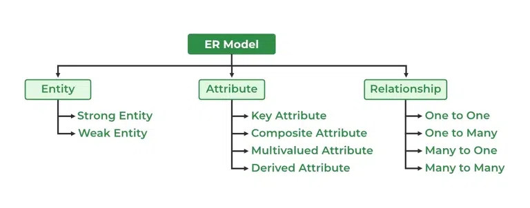
2. Key Components of the ER Model
- Entity:
- Definition: An entity is any object or thing that has a physical existence and can be distinctly identified.
- Example: A “Student” can be an entity in a university database.
- Attributes:
- Definition: Attributes are the characteristics or properties of an entity.
- Example: For a Student entity, typical attributes include roll number, age, address, and mobile number.
- Relationship:
- Definition: A relationship (or association) represents how two or more entities are connected.
- Example: Consider two entities—Student and Course. The relationship might be “studies,” meaning that a student studies a course. This relationship can also have a name (e.g., “Enrolls”) to clarify the connection between the entities.
3. Diagrammatic Representation
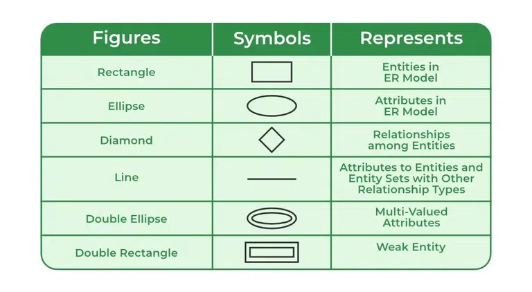
- Symbols Used:
- Entity: Represented by a rectangle.
- Attribute: Represented by an ellipse.
- Relationship: Represented by a diamond.
- Visual Clarity:
Using these symbols, one can create a diagram that shows entities, their attributes, and the relationships between them. This visual representation helps both technical teams and stakeholders understand the logical structure of the database before any coding begins.
4. The Process of Translating Requirements into the ER Model
-
Gathering Requirements:
Just as you would discuss building requirements with a client, you first gather all necessary information from the stakeholders. This might involve talking about what data needs to be stored (like student information, course details, etc.) and how that data is interrelated. -
Creating the ER Diagram:
With the gathered requirements, you then create an ER diagram that outlines:- Entities (like Student, Course)
- Attributes for each entity (e.g., for Student: roll number, age, address)
- Relationships between entities (e.g., a student “studies” a course)
-
Review and Approval:
This ER model is shared with the stakeholders (for example, the school principal) for review. Once approved, it serves as a blueprint for the implementation team to create the actual database using SQL commands such as CREATE TABLE, etc.
5. Advantages of Using the ER Model
-
Logical Organization:
The ER model organizes data in a logical and structured way, which simplifies the understanding of complex systems. -
Ease of Modification:
Changes can be made at the conceptual level without immediate impact on the physical implementation, reducing the need for extensive rework. -
Foundation for Database Implementation:
The ER model acts as a guide for translating the conceptual design into a relational schema. Once the design is finalized, it can be implemented using SQL in a DBMS, ensuring that the final database meets the specified requirements.
Types of attributes in ER model
https://www.geeksforgeeks.org/types-of-attributes-in-er-model/
https://www.youtube.com/watch?v=WEo3g6Ir-vA&list=PLxCzCOWd7aiFAN6I8CuViBuCdJgiOkT2Y&index=16
1. Single-Valued vs. Multi-Valued Attributes
-
Single-Valued Attributes:
These attributes hold exactly one value for a given entity instance.-
Example:
A student’s registration number or roll number. Even if other information like name or address might be common among multiple students, the registration number is unique and appears only once per student. -
Representation in ER Diagrams:
Typically drawn with a single ellipse.
-
-
Multi-Valued Attributes:
These attributes can hold multiple values for a single entity.-
Example:
A student’s mobile number can include more than one contact number, or a student might have multiple addresses (e.g., permanent and correspondence addresses). -
Representation in ER Diagrams:
Often depicted with a double ellipse to indicate that the attribute can have more than one value.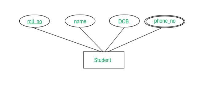
-
2. Simple vs. Composite Attributes
-
Simple Attributes:
These attributes cannot be divided into smaller parts; they are atomic.-
Example:
The age of a student is a simple attribute since the value (e.g., 20) is a single, indivisible unit.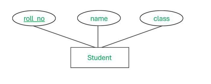
-
-
Composite Attributes:
These attributes can be broken down into smaller subparts, each representing a more basic attribute.-
Example:
A student’s name can be considered composite because it may consist of a first name, middle name, and last name. -
Utility:
Breaking down composite attributes can help in better organizing and querying the data.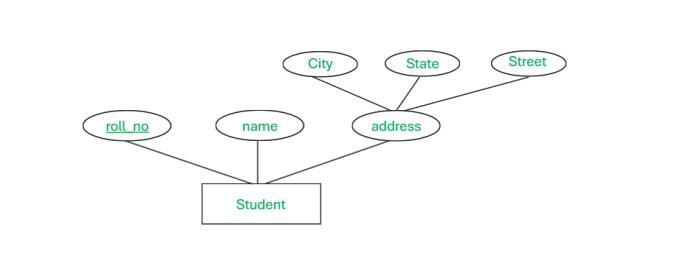
-
3. Stored vs. Derived Attributes
- Stored Attributes:
These are attributes whose values are directly stored in the database.-
Example:
Date of birth is stored as given by the user.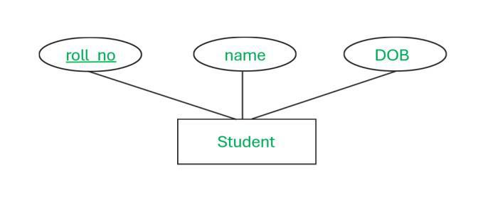
-
- Derived Attributes:
These are not stored directly; their values are computed or derived from other stored attributes.-
Example:
Age can be derived from the student’s date of birth and the current date. -
Representation in ER Diagrams:
Derived attributes are often shown using a dotted ellipse to distinguish them from stored attributes.
-
4. Key Attributes vs. Non-Key Attributes
- Key Attributes:
These attributes uniquely identify each instance of an entity.- Example:
A student’s registration or roll number is unique to each student. - Representation:
In ER diagrams, key attributes are typically underlined to indicate their uniqueness.
- Example:
- Non-Key Attributes:
These attributes do not uniquely identify an entity and may have duplicate values across instances.- Example:
Attributes like student name, father’s name, or date of birth may be the same for multiple students.
- Example:
5. Required vs. Optional Attributes
- Required (Mandatory) Attributes:
These must have a value for the entity; they cannot be left blank.- Example:
In many systems, the student name might be mandatory. - Practical Aspect:
When designing forms (or a database schema with NOT NULL constraints), these attributes are enforced so that critical data is always provided.
- Example:
- Optional Attributes:
These are not mandatory and can be left empty (NULL).- Example:
An alternate mobile number or a secondary address might be optional. - Usage:
The decision on whether an attribute is required or optional depends on the business rules and the importance of the information.
- Example:
6. Complex Attributes
- Complex Attributes:
Sometimes, attributes can be both composite and multi-valued.-
Example:
Consider an address attribute that is composite (divided into street, city, state, etc.) and multi-valued (if a student has more than one residential address). -
Significance:
These require a more detailed representation in the design since they capture a richer set of information.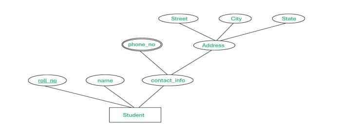
-
Types of relationships in ER Model (not the ones you’re thinking of)
1. Understanding Relationships in ER Models
-
Definition of a Relationship:
A relationship (or association) defines how two entities are connected. In the ER model, relationships show the way in which data in one entity relates to data in another. -
Types of Relationships (Cardinality):
- One-to-One (1:1)
- One-to-Many (1:N)
- Many-to-One (N:1)
- Many-to-Many (M:N)
For clarity, the many-to-many relationship is often noted as M:N to avoid confusion.
2. Focusing on One-to-One Relationships
-
Concept:
In a one-to-one relationship, each instance of one entity is associated with exactly one instance of the related entity.- Example:
An employee is assigned to one department, and each department has one specific employee designated (for example, as a head or a unique relationship).
- Example:
-
Why It’s Important:
Although a one-to-one relationship seems straightforward, the deeper concept involves how it is implemented in a relational schema and how it ensures data consistency without duplicates.
3. Implementing One-to-One Relationships in the Relational Model
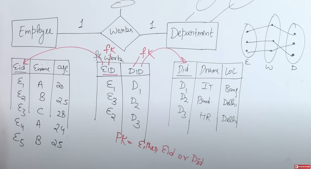
-
Entities as Tables:
- Employee: With attributes such as Employee ID (EID), name, and age.
- Department: With attributes like Department ID (DID), department name, and location.
Each of these entities is converted into its own table, and both tables have a primary key (EID for employees and DID for departments) to ensure uniqueness.
-
Relationship Table (Bridge Table):
To capture the association between employees and departments, a separate relationship table—often named “Work” in the example—is created.- Attributes in the Relationship Table:
At a minimum, it contains:- Employee ID (EID) as a foreign key referencing the Employee table.
- Department ID (DID) as a foreign key referencing the Department table.
- Descriptive Attributes:
The relationship table may also include additional descriptive attributes if needed (such as the date when the employee joined the department).
- Attributes in the Relationship Table:
-
Enforcing One-to-One:
In a one-to-one relationship, the relationship table must be designed so that neither EID nor DID appears more than once.- Primary Key Choice:
Since the relationship is one-to-one, you can choose either the Employee ID or the Department ID as the primary key for the relationship table because both are unique in their respective tables. - Data Consistency:
For example, if Employee E1 is associated with Department D1, E1 should appear only once in the relationship table and be linked solely to D1. Any attempt to associate E1 with a different department would break the one-to-one rule.
- Primary Key Choice:
4. Merging Tables in One-to-One Relationships
-
Why Merge?
If a one-to-one relationship exists, you might not need a separate relationship table. Instead, you can merge the two tables.-
How It Works:
For instance, if you choose EID (employee ID) as the primary key for the relationship, you can merge the Employee and Department tables into one unified table. -
Merged Table Structure:
The merged table would include:- Employee attributes (EID, name, age, etc.)
- Department attributes (DID, department name, location, etc.)
In this case, attributes from both entities appear in a single table, and the uniqueness of EID ensures that the relationship remains one-to-one.
-
Handling Nulls:
If not every employee is associated with a department, the department-related fields may be left as NULL. However, the primary key (EID) must never be NULL.
-
-
Final Table Count:
With proper merging in a one-to-one relationship, you may end up with two tables overall: one for the merged entities (or one if fully merged) and one for any additional unrelated data.
One to Many Relationship
https://www.youtube.com/watch?v=rZxETdO_KUQ&list=PLxCzCOWd7aiFAN6I8CuViBuCdJgiOkT2Y&index=18
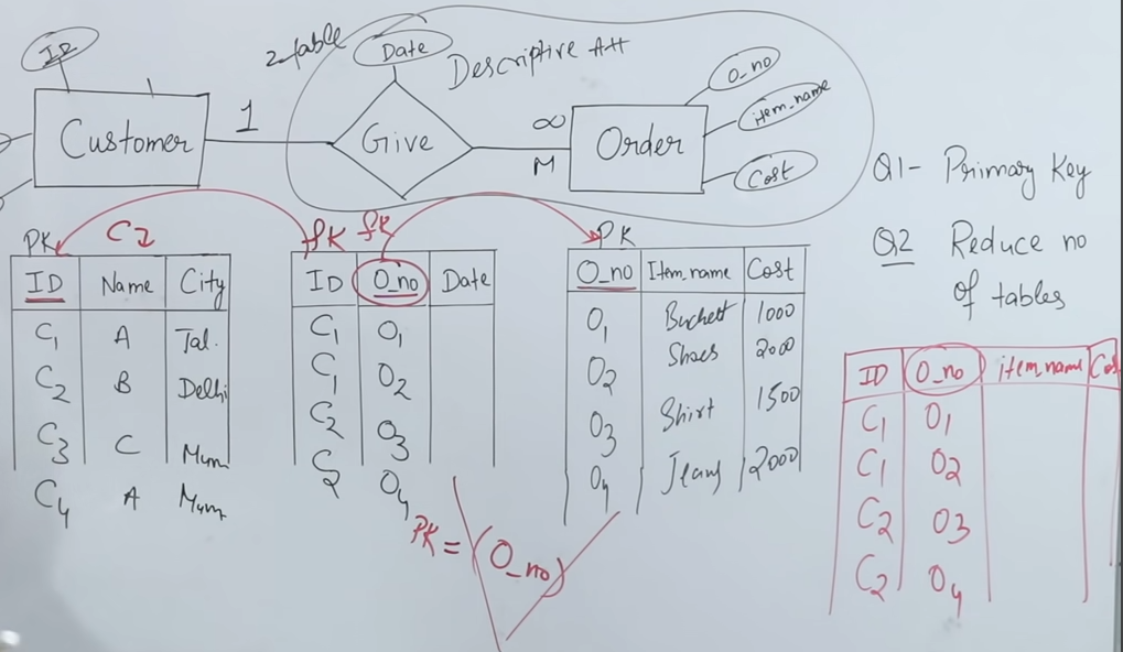
-
Definition and Basic Concept:
- A one-to-many relationship exists when one instance of an entity (for example, a customer) can be associated with multiple instances of another entity (for example, orders), but each order is associated with only one customer.
- In diagrammatic notation, this is often represented as “1 to M” (or 1 to infinity), indicating that one customer can give many orders.
-
Conversion to the Relational Model:
- Entity Tables:
- Customer Table: Contains customer attributes, including a unique identifier (ID) that serves as the primary key.
- Order Table: Contains order attributes, with order number as its primary key.
- Relationship Table:
- In addition to the two entity tables, a relationship table (representing the “gives” association) is created.
- This relationship table must contain two mandatory attributes:
- Customer ID (foreign key referencing the Customer table)
- Order Number (foreign key referencing the Order table)
- It may also include additional descriptive attributes (for example, the date when the order was placed).
- Entity Tables:
-
Ensuring Data Integrity in the Relationship Table:
- Since the relationship is one-to-many, the same customer ID may appear multiple times in the relationship table (reflecting that a customer can place multiple orders), but each order number will appear only once because each order belongs to one customer.
- Consequently, in the relationship table, the order number (from the “many” side) serves as the primary key, ensuring that each order is uniquely identified.
-
Merging Tables to Optimize the Schema:
- If the relationship is strictly one-to-many, the relationship table can sometimes be merged with the table on the “many” side (in this case, the Order table).
- Merging is possible because the primary key on the many side (order number) is unique and can serve to join the related data.
- However, you cannot merge the Customer table with the relationship table because the customer ID appears repeatedly in the relationship table (due to the one-to-many nature), and only the unique side (order number) can be used as a primary key after merging.
-
Key Takeaways:
- In a one-to-many relationship, the side representing “many” (orders) has the unique attribute (order number) that will act as the primary key in the relationship table.
- When converting the ER model to a relational model, you may initially have three tables (Customer, Order, and Relationship), but you can reduce them to two by merging the relationship table with the Order table.
- This approach maintains data integrity by ensuring that each order is linked to only one customer while allowing a customer to be associated with multiple orders.
Many-to-Many relationship
https://www.youtube.com/watch?v=onR_sLhbZ4w&list=PLxCzCOWd7aiFAN6I8CuViBuCdJgiOkT2Y&index=19
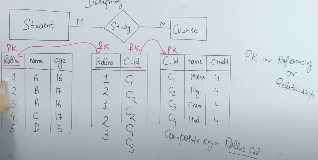
-
Definition of Many-to-Many Relationship:
- In a many-to-many (M:N) relationship, each instance of one entity can be associated with multiple instances of another entity, and vice versa.
- The example used is between the entities Student and Course with a “study” relationship: a student can study multiple courses, and a course can be taken by multiple students.
-
Representation in the ER Model:
- Entities:
- Student Entity: Typically includes attributes such as roll number (the primary key), name, and age.
- Course Entity: Typically includes attributes such as course ID (the primary key), course name, and credits.
- The many-to-many relationship is visually denoted as M:N (or MN), showing that both entities can have multiple associations with one another.
- Entities:
-
Conversion into the Relational Model:
- When converting the ER model into a relational model (using SQL), each entity is converted into its own table:
- A Student table with roll number as the primary key.
- A Course table with course ID as the primary key.
- To capture the many-to-many relationship, a separate relationship table (often representing the “study” relationship) is created. This table includes:
- Roll Number: Acts as a foreign key referencing the Student table.
- Course ID: Acts as a foreign key referencing the Course table.
- Descriptive Attributes: It may include additional attributes such as the date when the student enrolled in the course.
- When converting the ER model into a relational model (using SQL), each entity is converted into its own table:
-
Determining the Primary Key in the Relationship Table:
- In the relationship table, neither roll number nor course ID alone is unique because a student can appear in multiple rows (one for each course taken) and a course can be associated with multiple students.
- To uniquely identify each row in the relationship table, a composite primary key is created by combining roll number and course ID. This ensures that each record in the relationship table is unique.
-
Table Reduction (Merging) Consideration:
- While one-to-one or one-to-many relationships sometimes allow merging of tables (reducing the total number of tables), a many-to-many relationship cannot be reduced in this way.
- Because the relationship table’s primary key is a composite of roll number and course ID, the three tables (Student, Course, and the relationship table) must remain separate. They cannot be merged without losing the ability to accurately represent the many-to-many association.
1. Overview of Data Models
Data models provide the structure for storing, organizing, and manipulating data. They define how data is connected, how it is stored, and how it can be accessed. There are several types of data models, but today we’ll focus on three key ones:
- Network Data Model
- Relational Data Model
- Object-Oriented Data Model
Each of these models addresses the representation and handling of data differently.
2. Network Data Model
https://www.geeksforgeeks.org/network-model-in-dbms/
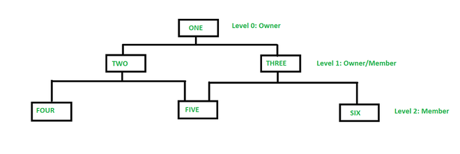
2.1 Key Characteristics
-
Graph-like Structure:
Data is represented as records connected by links. A record can have multiple parent and child records, forming a flexible, many-to-many relationship. -
Set Structures:
Relationships are modeled as sets where each set represents a one-to-many relationship between two record types. This means that while a record may be part of multiple sets, each set defines a specific relationship.
2.2 Advantages
-
Complex Relationships:
It efficiently represents many-to-many relationships, which are cumbersome in the relational model. -
Navigation Efficiency:
Traversal through data is often faster because the links between records are explicitly defined.
2.3 Drawbacks
-
Complexity in Querying:
Queries often require navigation through linked records rather than set-based operations, making ad-hoc queries more complex. -
Less Flexibility:
Modifying the schema (e.g., adding new types of relationships) can be more challenging than in a relational model.
2.4 Example
Imagine a telecommunications network:
- Records:
- Customer
- Service
- Contract
- Sets:
- A set might define the relationship “has contract with” between Customer and Contract, and another set could define “includes service” between Contract and Service.
3. Relational Data Model
https://www.geeksforgeeks.org/relational-model-in-dbms/
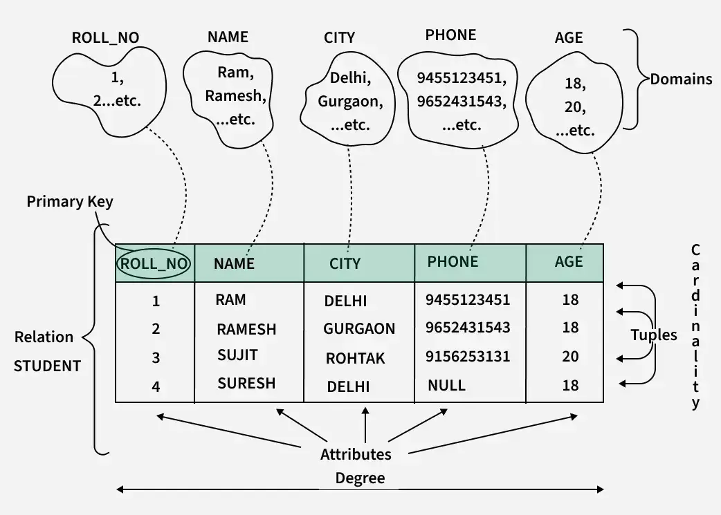
3.1 Key Characteristics
-
Tabular Format:
Data is organized into tables (relations) with rows and columns. Each row represents a record, and each column represents an attribute. -
Declarative Querying:
SQL (Structured Query Language) is used to perform queries, allowing you to specify what data to retrieve rather than how to retrieve it.
3.2 Advantages
-
Simplicity & Flexibility:
The tabular format is intuitive and lends itself well to ad-hoc querying. -
Strong Theoretical Foundation:
Supported by set theory and relational algebra, which provide a robust framework for query optimization and data integrity. -
Data Independence:
Changes to the physical storage or the internal schema generally do not affect the logical view provided by the relational model.
3.3 Drawbacks
-
Handling Complex Relationships:
While normalization helps reduce redundancy, representing very complex relationships (e.g., deep hierarchies) might be less intuitive. -
Performance Overheads:
The abstraction can introduce performance overheads if not properly indexed or if the data volume is very large.
3.4 Example
Consider a university database:
- Tables:
- Students (attributes: student_id, name, major)
- Courses (attributes: course_id, title, credits)
- Enrollment (attributes: student_id, course_id, semester)
- Relationships:
- The Enrollment table uses foreign keys (
student_id,course_id) to connect Students and Courses.
- The Enrollment table uses foreign keys (
4. Object-Oriented Data Model
https://www.geeksforgeeks.org/basic-object-oriented-data-model/
4.1 Key Characteristics
-
Encapsulation:
Data and its associated operations (methods) are bundled together into objects, mirroring real-world entities more closely. -
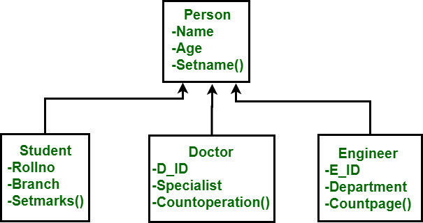
Inheritance:
Allows classes (or types) to inherit properties and methods from parent classes, facilitating reuse and reducing redundancy. -
Object Identity:
Each object has a unique identity independent of its attribute values, which supports complex relationships and behaviors.
4.2 Advantages
-
Real-World Modeling:
More naturally represents complex entities and relationships, especially in applications where behavior (methods) is as important as data. -
Reusability & Modularity:
Through inheritance and encapsulation, objects can be reused across different parts of an application.
4.3 Drawbacks
-
Querying Complexity:
The lack of a standard query language like SQL (though languages such as OQL have been developed) makes querying more challenging. -
Maturity & Adoption:
Object-oriented databases have seen less widespread adoption compared to relational databases, which might limit tool support and community resources.
4.4 Example
Imagine a multimedia library system:
- Objects:
- MediaItem (superclass) with attributes like title, publicationDate.
- Book and DVD (subclasses) inheriting from MediaItem but adding specific attributes (e.g., ISBN for books, duration for DVDs).
- Behavior:
Each object can have methods such asdisplayDetails()that are overridden by subclasses to show appropriate information.