Index
These are links to different sections within the note, won’t work in pdf form.
- What is a pipeline?
- Design of a basic pipeline
- Performance measuring of a pipeline
- Pipeline dependencies/ Hazards
- Types of Pipeline
- Pipeline optimization techniques
- Compiler Techniques for improving performance in the pipeline
Instruction level parallelism 1. Superscalar architecture 2. VLIW architecture 3. Superpipelined architecture. Difference between all the architectures.
Module 1
What is a pipeline?
Pipelining is a process of the arrangement of the hardware elements of the CPU such that it’s overall performance is increased. Simultaneous execution of more than one instruction takes place in a pipelined processor.
Design of a basic pipeline
- In a pipelined processor, a pipeline has two ends, an input end and the output end. Between these ends there are multiple stages/segments such that the output of one stage is connected to the input of the next stage and each stage performs a specific operation.
- Interface registers are used to hold the intermediate output between two stages. These interface registers are also called latch or buffer.
- All the stages in the pipeline along with the interface are controlled by a common clock.
Performance measuring of a pipeline
Performance of a pipeline is measured using two metrics, throughput and latency.
1. Throughput
- It measures the number of instructions per unit time.
- It represents overall processing speed of pipeline.
- Higher throughput indicates processing speed of pipeline.
- This is calculated as : “Number of instructions executed” / execution time
- Throughput is influenced by pipeline length, clock frequency, efficiency of instruction execution.
2. Latency
- It measures the time taken for a single instruction to complete it's execution.
- It represents delay or time it takes for an instruction to pass through pipeline stages.
- Lower latency indicates better performance.
- It is calculated as : Execution Time / Number of instructions executed
- It is influenced by pipeline length, depth, clock cycle, instruction dependencies and ==pipeline hazards.==
Pipeline dependencies/ Hazards
- Data Dependency
- Structural Dependency
- Control Dependency
These dependencies introduce stalls in the pipeline. A stall is a cycle in the pipeline without new input.
Structural Dependency.
This dependency exists due to resource conflicts in the pipeline.
The resource conflict is a situation in which, more than one instruction tries to access the same resource in the same cycle.
A resource can be a register, memory or ALU.
As shown in the instruction cycle below :
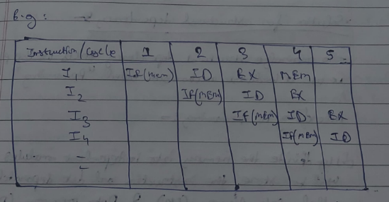
In this scenario, instructions I1 and I4 are trying to access the same resource MEM (memory) in the same cycle which causes a conflict. The instruction needs to be put on hold till the resource is available again. This unit period puts a stall in the pipeline as shown in the picture below:
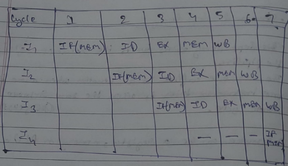
Here I4 has to wait till 3 clock cycles to access MEM again.
Solution for the structural dependency
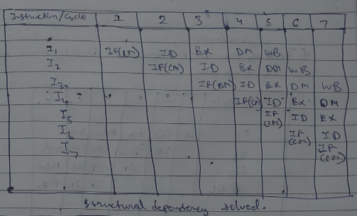
To minimize structural dependency, we use a hardware mechanism called "Renaming".
According to Renaming:
- We divide the memory into independent modules, which is used to store instructions and data separately, called Code Memory (CM) and Data Memory (DM).
- CM will contain all instructions and DM will contain all the operands (or variables).
Control Dependency (BRANCH Hazards)
This type of dependency occurs during the transfer of control instructions such as BRANCH, CALL, JMP, etc.
On many architectures, the processor will not know the target address, of these instructions when it needs when it needs to insert the new instruction into the pipeline. Due to this, unwanted instructions are fed into the pipeline.
For example, take the following instruction sequence :
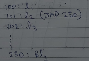
Here the target address (250) is only known after the IO stage.
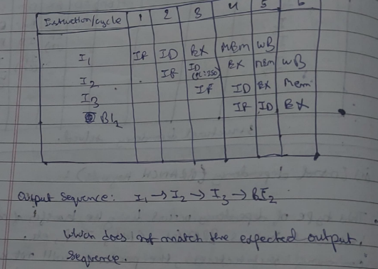
Solution for the Control dependency
We introduce a delay in the pipeline.
(Temporary solution)
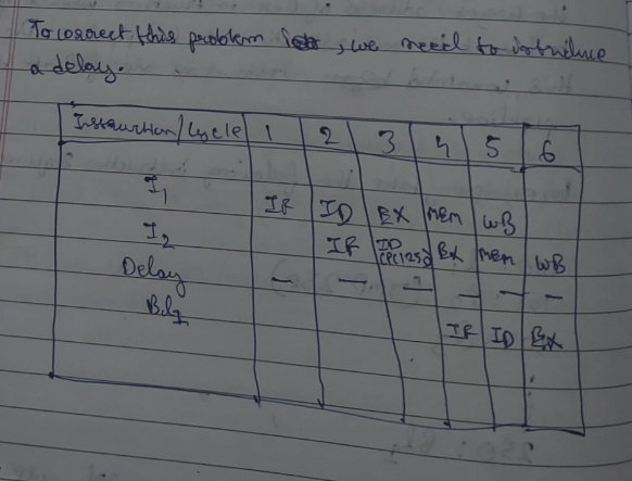
Data Hazards
Data hazards occur when instructions that exhibit data dependence, modify data in different stages of a pipeline. Hazard cause delays in the pipeline.
There are mainly three types of data hazards:
- RAW (Read after Write) [Flow/True data dependency]
- WAR (Write after Read) [Anti-Data dependency]
- WAW (Write after Write) [Output data dependency]
For example:
Let there be two instructions I and J, such that J follow I. Then:
- Instruction depend on result of prior instruction still in the pipeline.
- It can occur among the operands in the instruction at the pipeline stages.
- It occur when instructions read or write registers that are used by other instructions.
-
- RAW hazard occurs when instruction J tries to read data before instruction I writes it. Eg: I: R2 ← R1 + R3 J: R4 ← R2 + R3
- WAR hazard occurs when instruction J tries to write data before instruction I reads it. Eg: I: R2 ← R1 + R3 J: R3 ← R4 + R5
- WAW hazard occurs when instruction J tries to write output before instruction I writes it. Eg: I: R2 ← R1 + R3 J: R2 ← R4 + R5
Exceptions and Interrupts
Exceptions and interrupts are unexpected events which will disrupt the normal flow of execution of instructions that is currently being executed by the processor.
An exception is an event from within the processor.
An interrupt is an event from outside the process.
Whenever an exception/interrupt occurs, the hardware starts executing the code that performs an action in response to the exception. This may involve killing a process, outputting an error message, or horribly crashing the entire computer system by initiating a BLUE SCREEN OF DEATH and halting the CPU
Exception and Interrupt Handling
Whenever an exception or interrupt occurs, execution transitions from user mode to kernel mode where the exception or interrupt is handled. In detail, the following steps must be taken to handle an exception or interrupts.
While entering the kernel, the context (values of all CPU registers) of the currently executing process must first be saved to memory. The kernel is now ready to handle the exception/interrupt:
- Determine the cause of the exception/interrupt.
- Handle the exception/interrupt.
When the exception/interrupt have been handled the kernel performs the following steps:
- Select a process to restore and resume.
- Restore the context of the selected process.
- Resume execution of the selected process.
A detailed example (read this only if you have time) :
The exception/interrupt handler uses the same CPU as the currently executing process. When entering the exception/interrupt handler, the values in all CPU registers to be used by the exception/interrupt handler must be saved to memory. The saved register values can later restored before resuming execution of the process.
The handler may have been invoked for a number of reasons. The handler thus needs to determine the cause of the exception or interrupt. Information about what caused the exception or interrupt can be stored in dedicated registers or at predefined addresses in memory.
Next, the exception or interrupt needs to be serviced. For instance, if it was a keyboard interrupt, then the key code of the key press is obtained and stored somewhere or some other appropriate action is taken. If it was an arithmetic overflow exception, an error message may be printed or the program may be terminated.
The exception/interrupt have now been handled and the kernel. The kernel may choose to resume the same process that was executing prior to handling the exception/interrupt or resume execution of any other process currently in memory.
The context of the CPU can now be restored for the chosen process by reading and restoring all register values from memory.
The process selected to be resumed must be resumed at the same point it was stopped. The address of this instruction was saved by the machine when the interrupt occurred, so it is simply a matter of getting this address and make the CPU continue to execute at this address.
Types of Pipeline
- Instruction pipeline
- Arithmetic pipeline
1. Instruction Pipeline
An instruction pipeline receives sequential instructions from memory while prior instructions are implemented in other portions. Pipeline processing can be seen in both the data and instruction streams
Pipeline processing can happen not only in the data stream but also in the instruction stream. To perform tasks such as fetching, decoding and execution of instructions, most digital computers with complicated instructions would require an instruction pipeline.
In general, each and every instruction must be processed by the computer in the following order:
-
Fetching the instruction from memory
-
Decoding the obtained instruction
-
Calculating the effective address
-
Fetching the operands from the given memory
-
Execution of the instruction
-
Storing the result in a proper place
Each step is carried out in its own segment, and various segments may take different amounts of time to process the incoming data. Furthermore, there are occasions when multiple segments request memory access at the very same time, requiring one segment to wait unless and until the memory access of another is completed.
A four-segment instruction pipeline unifies two or more distinct segments into a single unit. For example, the decoding of the instruction and the calculation of the effective address can be merged into a single segment.
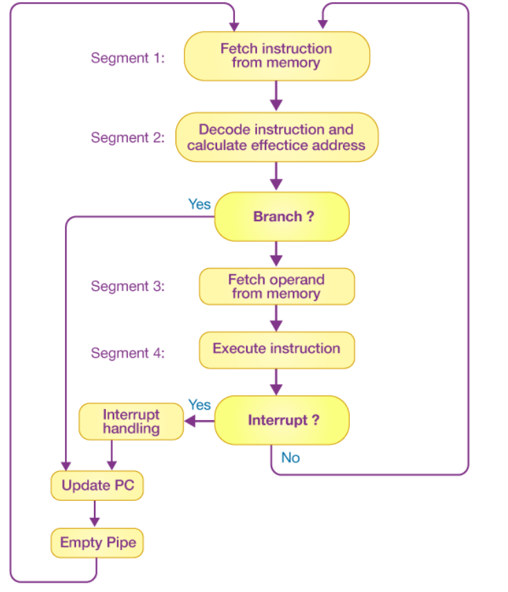
A four-segment instruction pipeline is illustrated in the block diagram given above. The instructional cycle is divided into four parts:
Segment 1
The implementation of the instruction fetch segment can be done using the FIFO or first-in, first-out buffer.
Segment 2
In the second segment, the memory instruction is decoded, and the effective address is then determined in a separate arithmetic circuit.
Segment 3
In the third segment, some operands would be fetched from memory.
Segment 4
The instructions would finally be executed in the very last segment of a pipeline organization.
2. Arithmetic Pipeline
An arithmetic pipeline separates a given arithmetic problem into subproblems that can be executed in different pipeline segments. It’s used for multiplication, floating-point operations, and a variety of other calculations.
Arithmetic Pipelines are commonly used in various high-performance computers. They are used in order to implement floating-point operations, fixed-point multiplication, and other similar kinds of calculations that come up in scientific situations.
Example :
The inputs in the floating-point adder pipeline refer to two different normalized floating-point binary numbers. These are defined as follows:
Where x and y refer to the exponents and X and Y refer to two fractions representing the mantissa.
The floating-point addition and subtraction process is broken into four pieces. The matching sub-operation to be executed in the specified pipeline is contained in each segment. The four segments depict the following sub-operations:
-
Comparing the exponents using subtraction
-
Aligning the mantissa
-
Adding or subtracting the mantissa
-
Normalizing the result
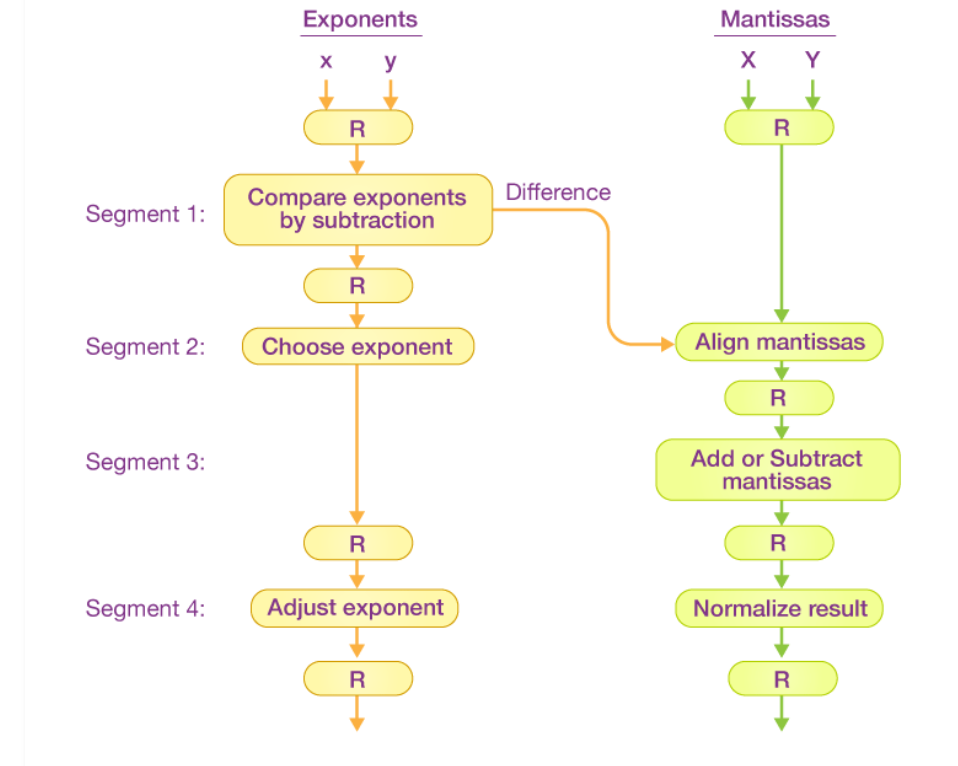
The registers are placed after every sub-operation in order to store the intermediate results.
1. Comparing Exponents by Subtraction
The difference between the exponents is calculated by subtracting them. The result’s exponent is chosen to be the larger exponent.
The exponent difference, 3 – 2 = 1, defines the total number of times the mantissa associated with the lesser exponent should be shifted to the right.
2. Aligning the Mantissa
As per the difference of exponents calculated in segment one, the mantissa corresponding with the smaller exponent would be moved.
3. Adding the Mantissa
Both the mantissa would be added in the third segment.
4. Normalizing the Result
After the process of normalization, the result would be written as follows:
Pipeline optimization techniques:
1. Pipeline Depth and Stage Balancing
- Deep Pipelining: Increasing the number of stages in a pipeline can enhance the clock speed, but it also increases the complexity and the potential for hazards.
- Stage Balancing: Ensuring that each pipeline stage takes roughly the same amount of time helps avoid bottlenecks and improves overall efficiency.
2. Hazard Mitigation
- Data Hazards: Techniques like forwarding (bypassing) and hazard detection units help mitigate issues when instructions depend on the results of previous ones.
- Control Hazards: Branch prediction and speculative execution are used to minimize the delay caused by control dependencies.
- Structural Hazards: Adding more resources (e.g., additional functional units) can help avoid conflicts when multiple instructions require the same hardware resources.
3. Superscalar and Superpipelining
- Superscalar: Multiple instructions are issued and executed per clock cycle by providing multiple execution units.
- Superpipelining: Increases the clock speed by reducing the time taken for each pipeline stage, effectively splitting stages into smaller sub-stages.
4. Instruction Level Parallelism (ILP)
- Linked to Superscalar and Superpipelining: Increasing the instruction throughput to reduce the overhead of loop control instructions.
- More on this below during module 3 section
5. Compiler Techniques
- Instruction Scheduling: Rearranging the order of instructions to avoid pipeline stalls.
- Register Allocation: Efficiently managing the use of registers to reduce memory access and pipeline stalls.
Compiler Techniques for improving performance in the pipeline
Compiler techniques play a crucial role in optimizing the performance of the instruction pipeline in a CPU. These techniques focus on improving instruction scheduling, reducing hazards, and enhancing resource utilization.
Here are some compiler techniques for improving performance in the pipeline:
1. Instruction Scheduling
Instruction scheduling is a key optimization technique where the compiler rearranges the order of instructions to avoid pipeline stalls and maximize instruction throughput.
- Static Scheduling: The compiler analyzes the code at compile time and reorders instructions to minimize pipeline stalls. This is done by ensuring that data dependencies are respected while filling in delay slots caused by branches or other hazards.
- Dynamic Scheduling: In some cases, dynamic scheduling is employed at runtime by the hardware, but compilers can assist by providing hints or optimized sequences that can be dynamically adjusted.
2. Loop Unrolling
Loop unrolling is a technique where the compiler replicates the loop body multiple times, reducing the overhead of loop control instructions and increasing instruction-level parallelism.
- Example: Transforming a loop that iterates 100 times into a loop that iterates 25 times, with each iteration performing four times the original work.
3. Software Pipelining
Software pipelining involves reordering instructions from different iterations of a loop so that multiple iterations are overlapped, increasing parallelism and reducing idle time in the pipeline.
- Example: In a loop, the computation for the next iteration can begin before the current iteration finishes, effectively keeping all parts of the pipeline busy.
4. Register Allocation
Efficient register allocation minimizes the use of memory accesses, which are slower and can cause pipeline stalls.
- Graph Coloring: A common method where the compiler uses a graph to represent register interference and assigns registers in a way that minimizes conflicts.
- Spilling: When there are not enough registers, some variables are temporarily stored in memory. The compiler tries to minimize spilling by optimizing register usage.
5. Dead Code Elimination
Removing code that does not affect the program’s output can reduce the number of instructions and potential pipeline stalls.
- Example: Eliminating computations whose results are never used.
Module 3
Instruction level parallelism
Instruction level parallelism is a measure of how many of the operations in a computer program can be executed simultaneously.
What is parallelism in terms of CPU?

As the above diagram states, this processor with 4 sub processors can break down a program in 4 small parts and execute these parts simultaneously.
The problem of Shared Dependency.
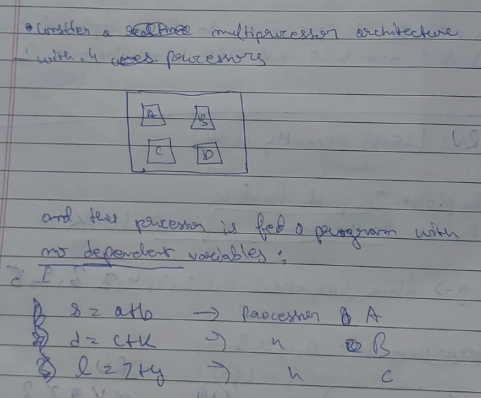
Here the same processor can break down the program into three separate instructions and execute them simultaneously.
All three instructions are processed simultaneously in 1 unit time.
Now take another set of instructions :
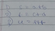
Here as you can see in instruction 3, operand u is dependent on the values of the previous operands s and t.
So all three instructions cannot execute in unit time as instruction 3 needs to be put on hold for the values of the previous two operands, which introduces a stall in the processor.
Thus,
This phenomenon of stalling in a processor due to incomplete data is called the problem of shared dependency.
Now, to calculate the maximum level of parallelism that can be exploited in a program is a ratio called the ILP ratio.
It is calculated by ILP = Total number of instructions / Total time taken to execute the instructions
In the second program’s case the ILP ratio is 3/2.
The higher the ILP ratio, the better it’s throughput is.
Or we can say that throughput is inversely related to latency.
Architectural techniques to increase ILP
- Superscalar architecture
- VLIW
- Superpipelining
1. Superscalar architecture
Let’s see how a traditional instruction pipeline works:

Here
IF = Instruction Fetch ID = Instruction Decode EX = Execute MEM = Memory WB = Writeback
In this architecture only a single instruction gets executed in a single unit time.
Now, in case of a single instruction, once fetching is done, IF stays idle till the current execution is complete. Once Decoding is done, ID stays idle till the current execution is complete.
And this goes on, decreasing productivity of the processor and the overall throughput is reduced.
Hence, enter, Superscalar Architecture

==Basically what happens here that in the first instruction As soon as the fetching is done, the fetching of the next instruction starts, while the first instruction is being decoded.==
This architecture works on a cascading domino style where subsequent operations are triggered as soon as the resource for the previous operation is freed.
Another easy to understand example diagram could be :
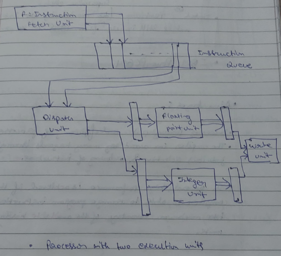

In each cycle, the dispatch unit retrieves and decodes up to two instructions from the front of the queue. If it is one integer, one floating point number and no hazards, then both the instructions are dispatched in the same clock cycle.
2. VLIW architecture
VLIW stands for “Very long instruction Word”
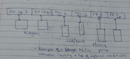
Contrary to the superscalar architecture, the VLIW architecture follows the principle of ==putting a single large instruction in which involves a lot of different parts of a CPU finishing 2-3 or more tasks in a single instruction cycle==.
We could also view it as combining 2-3 or more tasks in a single instruction cycle.
However it is not necessary that a CPU dealing with VLIW has only one of each component(ALU, MU, CU).
An ideal CPU following VLIW has more than one components (each) to deal with large instructions.
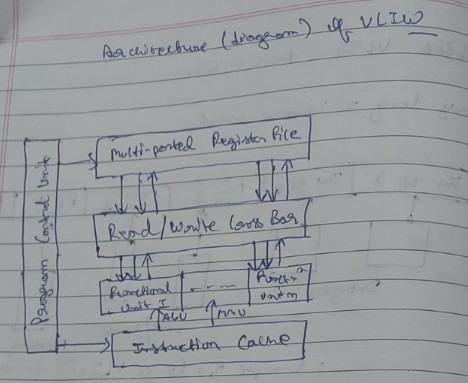
In the above digrammatical representation of the VLIW architecture,
Instructions are stored in the instruction cache where according to each instruction, a final unit is assigned(ALU or MU)
Operands are stored in the multi-ported register file where they are fetched for instructions
The control unit manages the overall functioning of the architecture.
The functional units execute instructions and pass them to read/write cross bar where it is decided what to do with the completed instructions.
3. Superpipelined architecture.
A superpipelined architecture in computer architecture is an advanced form of pipelining where instructions are divided into smaller tasks and executed concurrently in multiple stages. It improves the performance of a standard pipeline by further reducing the execution time of instructions.
In a superpipelined architecture, each instruction goes through multiple stages such as
Instruction fetch (IF), Instruction decode (ID), Execute (EX), memory access (MEM) and write-back (WB).
The next instruction can be loaded while the current instruction is being executed (EX), allowing for a seamless flow of instructions, like an assembly line.
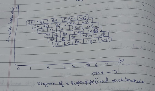
The diagram might look similar to superscalar, but the difference lies in the fact that in superscalar, things happen one after another, while in superpipelined architecture things happen at the same time, providing a huge difference in performance.
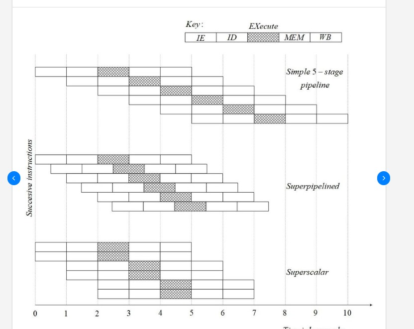 Diagram difference of superpipelined and superscalar architectures
Difference between all the architectures.
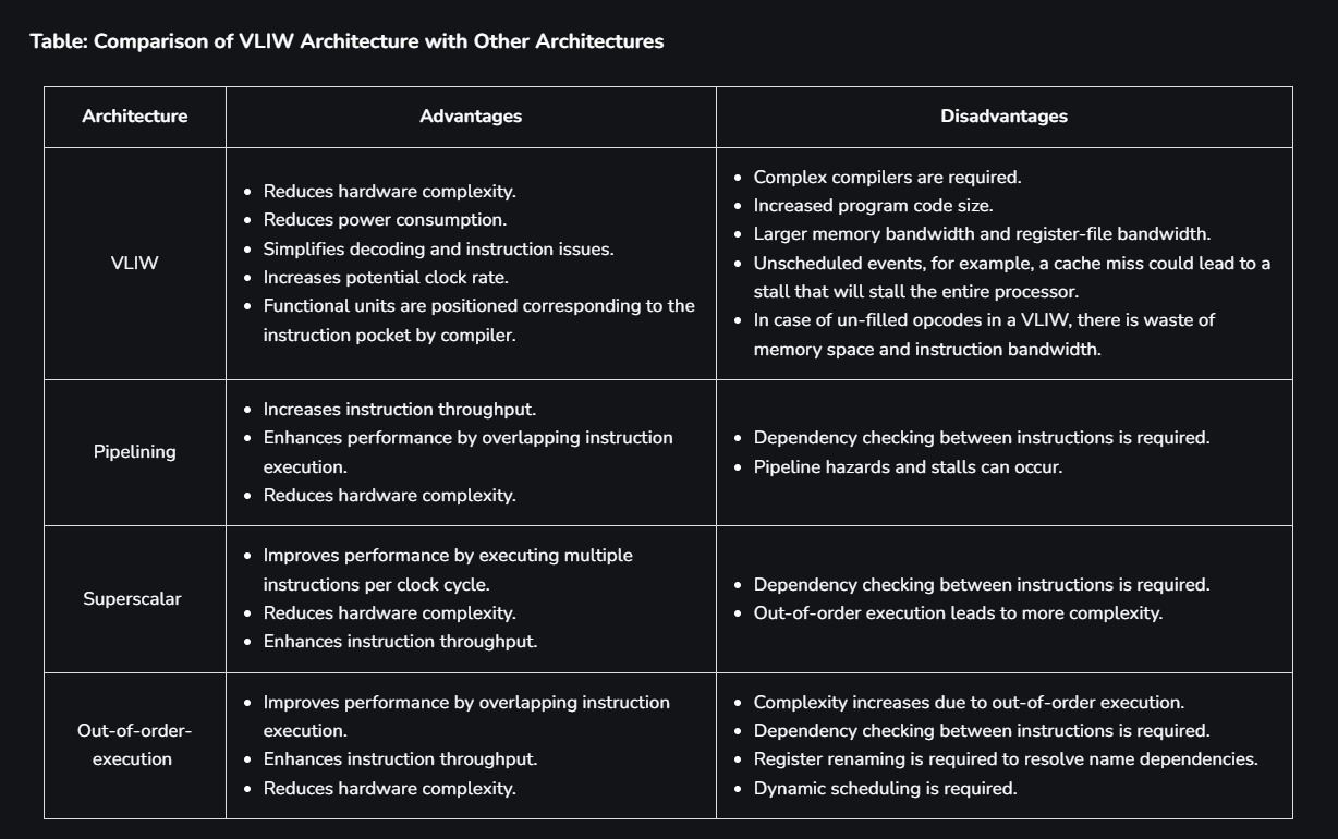
Ignore Out-of-Order-Execution.
Array processor onwards are continued in module 4 pdf.
