Index
- Memory Hierarchy
- Memory Hierarchy
- Cache Memory
- Cache Memory organizations and mapping techniques.
- Cache-Replacement Policies
Memory Hierarchy
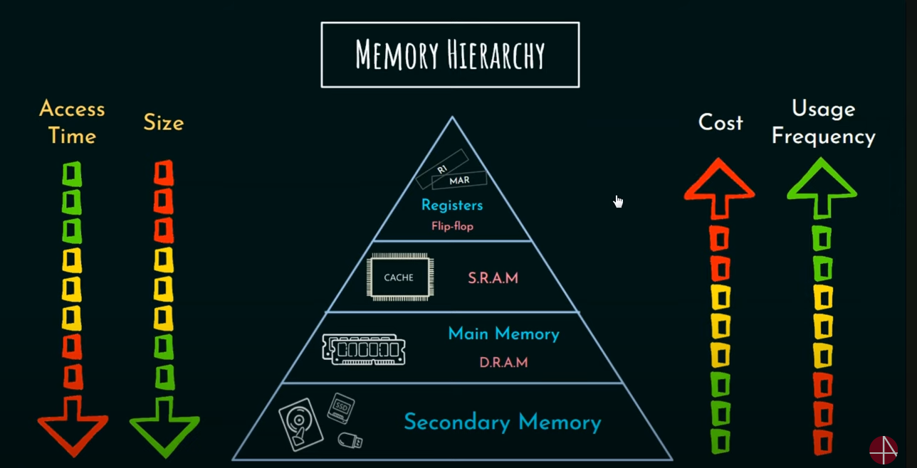
Here as we can see as the size of the memory decreases, access time decreases and the cost and usage frequency increases.
Note that the fastest memory in the computer is the process register, not the cache memory as commonly confused.
Cache Memory
Cache memory is a type of high speed memory used in computer architecture to temporarily store frequently accessed data. It acts as a buffer between main memory and the CPU, allowing for faster data, retrieval and improving overall system performance.
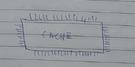
Sample example diagram of a cache.
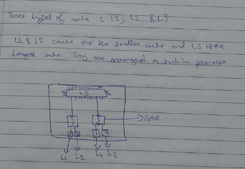
The L1, L2, and L3 caches are hierarchical layers of cache memory in a computer’s CPU, designed to improve processing speed by storing frequently accessed data. Here’s a brief explanation of each:
-
L1 Cache (Level 1):
- Location: Closest to the CPU cores.
- Speed: Fastest among the three caches.
- Size: Smallest, typically 16KB to 128KB per core.
- Purpose: Stores the most frequently accessed data and instructions.
-
L2 Cache (Level 2):
- Location: Between L1 and L3 caches, often shared by a core or a pair of cores.
- Speed: Slower than L1 but faster than L3.
- Size: Larger than L1, typically 256KB to 1MB per core.
- Purpose: Holds data and instructions that are accessed less frequently than those in L1.
-
L3 Cache (Level 3):
- Location: Shared across all cores within the CPU.
- Speed: Slowest among the three caches but faster than main memory.
- Size: Largest, typically 2MB to 45MB or more.
- Purpose: Stores data and instructions that are accessed less frequently than those in L1 and L2.
Each cache level serves to reduce latency and improve performance by providing quicker access to data compared to retrieving it from the main memory.
Locality of reference
There are two ways in which the processor decides by which data should be loaded onto the cache.
This is called ==locality of reference==.
- Spatial Locality
- Temporal Locality
Spatial Locality
Spatial Locality refers to the phenomenon where if a particular memory location is accessed, nearby memory locations are likely to be accessed soon. This principle is used in cache memory design, where data that is close to the recently accessed data, is loaded onto the cache.
Temporal Locality
Temporal locality refers to the likelihood that if a memory location is accessed now, it will probably be accessed again in the near future. This principle is used in cache design where recently accessed memory locations are kept in a fast memory or cache to reduce the required time to access it again.
Inclusion
Inclusion is a property of cache hierarchy in computer architecture that determines whether a subset of superset of the data is present in the next level of memory/cache.
There are two types of cache inclusion:
- Cache inclusion (duh) : A cache is said to be cache-inclusive if it contains a subset of the data present in the next level of cache/main memory. This means that any data present in the case is also present in the next level of cache/main memory.
- Cache exclusion: A cache is said to be cache-exclusive, if it contains a superset of the data present in the next level of cache/main memory. This means any data present in the cache is not present in the level of cache/main memory.
Cache inclusion simplifies and improves cache coherence and performance.
But it can increase cache size and access time as cache needs to store a large amount of time.
Cache coherence
It is a concept in computer architecture that data in multiple caches of a multiprocessor architecture should be consistent and up-to-date. When multiple processors access the same memory location, they may have their own local cache with different copies of the same data. Cache coherence ensures that when one processor modifies the data, changes are propagated to all other caches in the system.
This is important because if the caches are not kept coherent a processor will be working with outdated data, leading to inconsistencies and incorrect results. Cache coherence is maintained through various protocols, such as sweeping, directory based and message-based protocols.
Cache Memory organizations and mapping techniques.
Since the cache is limited in size, not all of the main memory can be mapped onto the cache as it is.
For this, mapping techniques are needed.
We have the following mapping techniques:
- Direct Memory Mapping
- Associative Mapping (or fully associative mapping)
- Set-associative Mapping
Important terminologies.
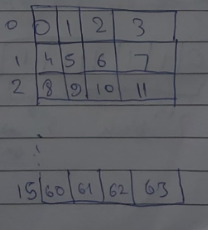
MM = Main memory Word = smallest representation of data in MM MM contains blocks Cache contains lines Size of block = Size of line Number of blocks != Number of lines
MM is referred to as P..A.S or the Physical Address Space
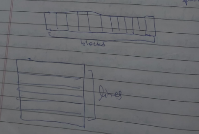
A sample diagram of blocks and lines (this is not actually how it is irl)
If each Word is of 1 bytes, then MM is known as a Byte-Addressable memory

Direct memory mapping (explanation via example)-
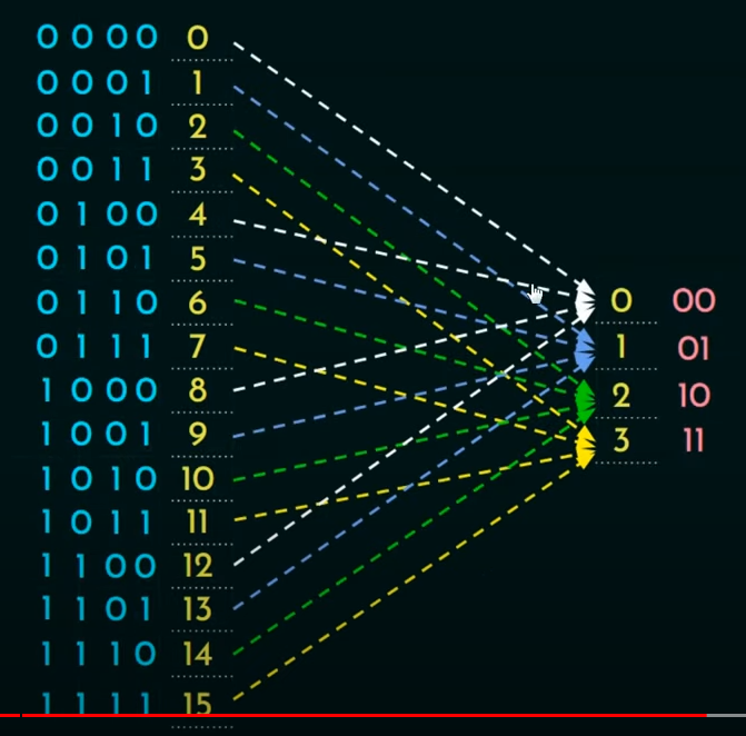
For video explanation
https://www.youtube.com/watch?v=V_QS1HzJ8Bc&list=PLBlnK6fEyqRgLLlzdgiTUKULKJPYc0A4q&index=8&pp=iAQB
For example, let there be a given MM size = 64 words
Therefore, P.A.S for this size is
which is 6 bit places

also given block size = 4 words
Therefore ==Number of blocks in MM== :
Thus 64 / 4 = 16
In this instance there are 16 blocks
There number of bits needed on the P.A.S to represent each block:
=
= 4 bits place needed.
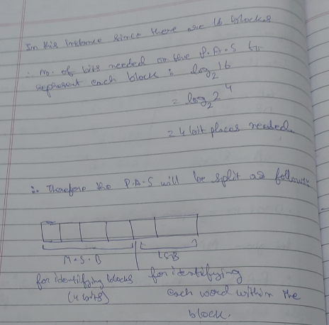
Therefore, M.S.B = (0000 to 1111) = 16 blocks L.S.B = (00 to 11) = 4 words in each block
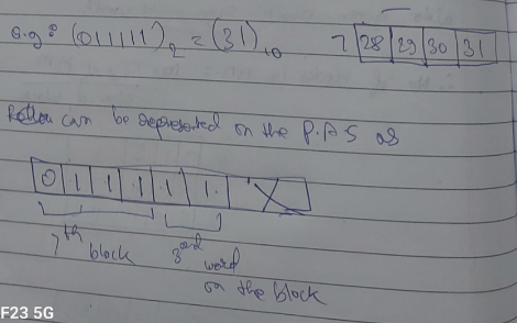

Now the mapping is done as follows.
The Round-Robin approach is used.
From the 16 blocks, first 4 blocks are mapped onto cache of line size 4, cache size = 16.
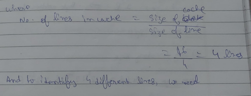
Since there are only 4 lines, not all of the MM blocks can be assigned together, mapping is needed.
Thus, with Direct memory mapping, every 4 block is assigned to the same set of blocks.
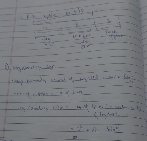
Thus the P.A split (Physical address split) accordingly will be:
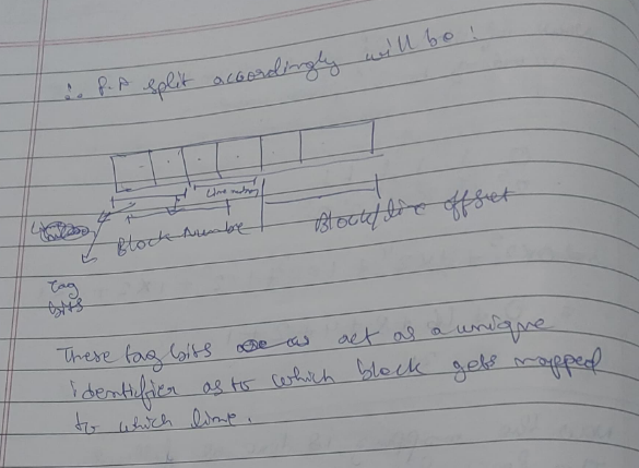
The block number bits hold the current number of the block with respect to the data of the block (block/line offset)
The tag bits act as a unique identifier as to which block gets mapped onto which line.
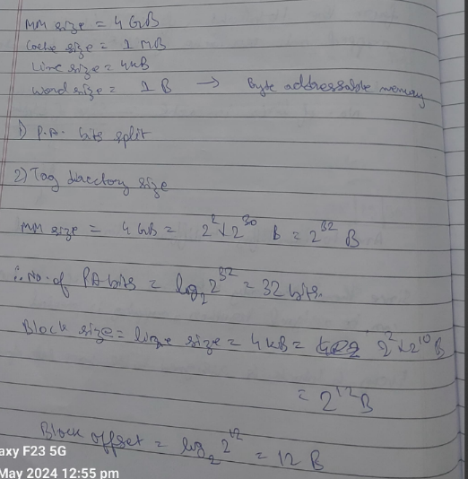
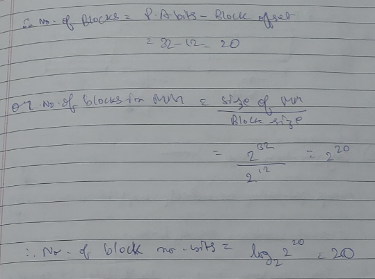
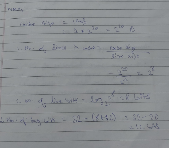
Example
Associative Mapping
There are some downsides of DMM, for example, when trying to retrieve some blocks, other blocks are evicted in the process, which causes cache misses and data loss.
This phenomenon is known as “conflict miss”.
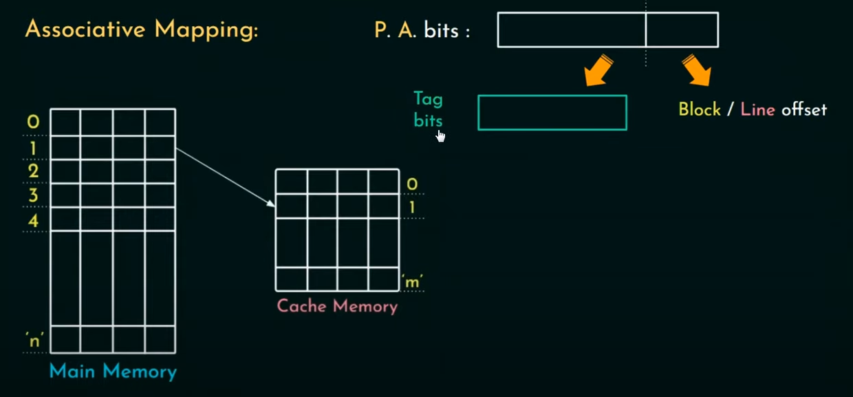
To resolve this: Associative mapping is brought into the picture where any block can be mapped to any line on the cache (Many-to-many relation).
In this type of mapping, the block number bits are replaced by Tag bits.
This introduces a disadvantage of it’s own however, in fully associative mapping, since it is a many to many relationship, there is no clue as to which line is mapped to which block, during retrieval. This increases the hit latency (time taken to fetch data from memory).
One solution to this is to add a lot of comparators in parallel to check the blocks against the lines, but this will only cost more and increase the heat.
Example
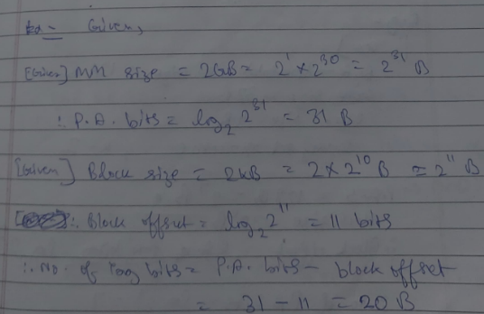 Find the Hit latency

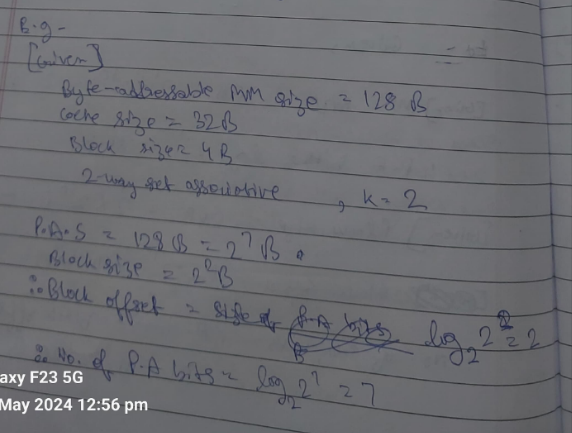
Set associative mapping
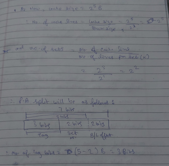
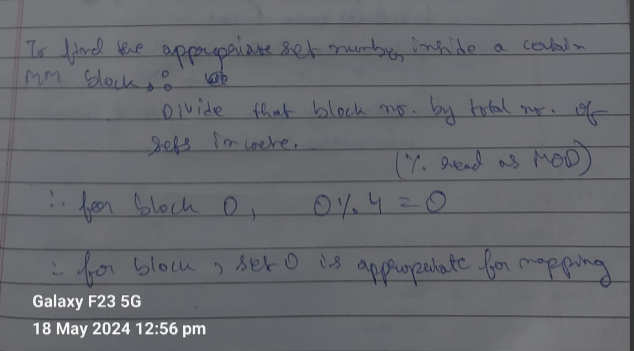
In this type of mapping, the cache lines are divided into a number of sets. Now, if a block of MM gets mapped onto a line belonging to a set, the block has the option of being mapped to any other line within that set.
All sets are of a fixed size (k) (1 set = k lines)
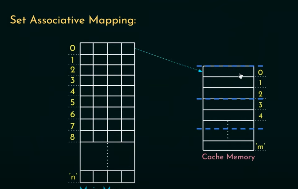
Thus if a cache is mapped as set associative, it is known as k-way associative
Example
Cache-Replacement Policies
What is Cache Replacement?
Cache replacement is required when the cache suffers from either conflict or cache miss.
In cache replacement we evict one block and make space for the newly requested block.
Which block to replace?
In DMM, no need for policies Under Associative and Set associative mapping, cache replacement policies are needed.
Types of cache replacement policies
- Random Replacement
- FIFO and LIFO
- Optimal Replacement
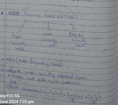
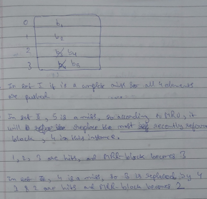
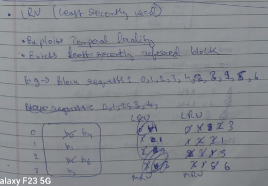
- Recency based policies
Sections here on out will contain pictures since time was short during the making of these notes.
1. Random Replacement

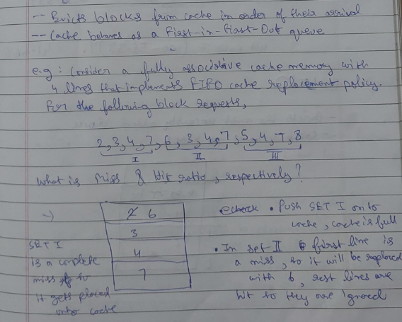
2. FIFO

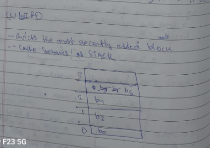
3. LIFO
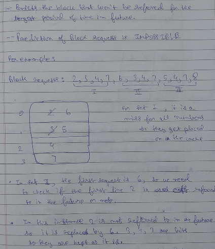
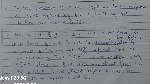
4. Optimal Replacement (skip if you don’t have time)

4. Recency based policies
